 |
|
CONSUMAT® modular, controlled air incinerators are inherently clean-running by design, with lower CO and Particulate emissions than many other technologies. Smoke free operation was a design criteria achieved from inception of the technology. Some emissions of concern, however, cannot be controlled by the combustion process alone. This is true of any combustion process including automobiles, wood burning stoves and lawn mowers.
The CONSUMAT® Dry Scrubber Fabric Filter technology was first introduced in 1986 to reduce these emissions. These efficient systems meet today's stringent air quality standards throughout the world.
The dry scrubber-baghouse emissions control system is designed to be an integral part of the incineration system. The dry scrubber is designed to operate continuously during start-up, operation, burn-down and cool-down of the systems. The major components of the system are as follows:
Gas Handling System
Various ducting is utilized to route combustion gases to each system within each processing train. The specific design of each component of ductwork is a function of the quantity and temperature of gases flowing through the duct.
In the normal operating mode, the combustion gases are drawn through the hot gas duct, the boiler, the dry scrubber system and the wet scrubber (if required) by the I.D. fan which discharges into the main stack. Precise control of the system "draft" is accomplished by a variable position damper at the inlet of the I.D. fan. Draft is sensed in the lower chamber by means of a differential pressure gauge/switch. The automatic controller directs the air operated control valve to move toward the open or closed position in response to actual draft conditions to maintain the desired draft.
Since the quantity of combustion gases will always be changing as a result of normal variations in the burning rate in the lower chamber, the induced draft fan control system must continually adjust to maintain a constant draft in the system.
Quench Chamber
The temperature of the flue gas as it leaves the boiler may be higher than the allowable temperature of
downstream components, particularly the fabric filter bags. The temperature must be reduced below the
critical temperature limitations of the these components. Additionally, permit conditions may require a
specific temperature prior to the scrubber system. This is accomplished by means of evaporative cooling in
the quench chamber. The quench chamber is fabricated of mild steel and the interior shell is coated with an
acid resistant mastic prior to installation of a refractory lining.
The gas temperature is reduced and humidified by controlled injection of water through a high efficiency, air
atomizing water spray nozzle. The rate of injection at the quench chamber inlet is determined by the
temperature of the gas at the quench chamber exit. The temperature is automatically monitored and
controlled by a digital controller which directs the proportional control of the quench water modulating valve.
The controls perform automatically to maintain temperature.
Mixing Chamber
The mixing chamber is a passive device and no controls are required. The conditioned flue gas enters the mixing chamber through a high velocity, cyclonic mixing tube. The reagent (hydrated lime or sodium bicarbonate) is introduced into the gas stream just before the mixing chamber inlet. The mixing chamber inlet is tangential to the cylindrical, vertical downflow vortex tube inside the main chamber to promote a swirling effect. The gases and reagent are mixed to promote contact between the reagent and gas as the flow is drawn down the tube before changing direction to exit at the top of the main mixing chamber. This chamber provides a turbulent zone with sufficient residence time to promote adequate mixing of the reagent and gas. Large micron particulate and reagent particles, too heavy to be entrained with the gas, fall to the bottom and are removed from the chamber by a conical hopper and discharged into the solids handling screw conveyor. The gases then flow from the mixing chamber exit to the inlet of the baghouse. The exterior of the main chamber is factory insulated and sheathed to maintain shell temperatures above the dewpoint (the temperature at which the acid laden gas condenses to form droplets) of the gas. A bolted access plate is provided for routine inspection of the chamber interior.
Fabric Filter Baghouse
The CONSUMAT® baghouse is a two compartment housing utilizing an array of fabric filter bags to clean the gas, as flow is induced through the filter bags by the I.D. fan. The compartments are separated by a cell plate or "tubesheet" with an array of 5 or 6" (nominal diameter) holes. Fabric filter bags are attached to the holes by means of an integral snap ring band at the top of the filter bag. This method of attachment provides a tight seal between the tubesheet openings and the bags. The bags are suspended into the "dirty gas side" of the module. The flue gases must pass through the fabric filters before exiting the "clean gas side" of the baghouse module. Particulate and reagent are retained on the outside of the bags as the gas passes through. The reagent deposited on the bag exterior ("cake") offers additional filtering media and opportunity for neutralization of acid gas, as the gas must pass through the filter bag before exiting. The flue gas and entrained reagent are drawn through the system by the induced draft fan. The negative pressure created by the fan would collapse the bags, if they were not supported. This support is provided by tube shaped wire cages inserted inside the bags.
The filter elements must be periodically cleaned to remove the accumulation of particulate and spent reagent. If the build-up was allowed to continuously increase, the pressure drop across the system would be difficult to overcome and would result in insufficient draft. Additionally, chemically spent reagent would offer decreased acid removal efficiency. The cleaning cycle is initiated automatically by monitoring the pressure drop across the baghouse. When the differential pressure reaches a preset limit (typically 4-6" W.C.), the bags are pulsed with a brief burst of compressed (dried) air. "Pulse jet" pipes are mounted above each row of bags with air nozzle holes located at the approximate center of each bag in the row. A solenoid valve is actuated to energize the pulse pipe with a short duration (approximately 0.5 seconds) burst of compressed air at 75-100 psig. The volume of air introduced into the bags is augmented by the effect of a venturi inlet, installed as an integral part of the support cage top. This air bubble travels down the length of the bag which causes the fabric to expand and flex outward, dislodging the dust "cake" which falls down into the discharge hopper for removal by the screw conveyor.
The CONSUMAT® Dry Scrubber Fabric Filter system employs a unique control design logic for efficient on-line pulsing of the filter bags. This logic helps avoid excessive and unnecessary pulsing, thereby reducing wear and extending the useful life of the bags.
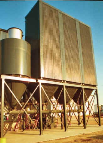
Reagent Feed System
The reagent feed system is designed to pneumatically convey the reagent into the scrubber system. A "day hopper" or large capacity silo (depending on facility size) provides storage capacity to permit uninterrupted flow of reagent. Automatic controls regulate the feed rate.
Optional Carbon Injection System
The carbon injection system is designed to pneumatically convey powdered, activated carbon into the scrubber system. A small hopper provides storage capacity to permit uninterrupted flow of reagent. Carbon injection is a proven method of dioxin control.